p&id drawing
The PID diagram software comes with a rich set of high-quality PID symbols for you to create different kinds of PID diagrams. Function and purpose of.

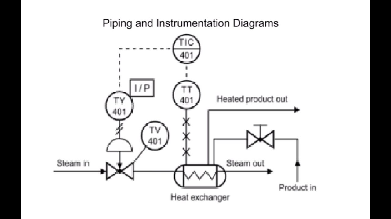
P Id Flow System Example P Id Diagram Piping And Instrumentation Diagram Example
A PID provides information to begin planning for.

. A diagram which shows the interconnection of process equipment and the instrumentation used to control the process. A Process and Instrumentation Diagram P ID shows the process flow and interconnection of process equipment which is used control a process. PID is a detailed diagram in the process industry which shows the piping and process equipment toget.
PIDs will include important piping details dimensions flow direction etc safety requirements and mechanical equipment needed. Without a doubt Visual Paradigm Online is the best PID software to create. Describe elements of the PID.
The PID is the primary schematic drawing used for laying out a process control systems installation. PID Instruments Location Now that we know our device FV01 is represented by a circle we can also tell from the PID where the instrument or device is located. Everyone can open an image PDF or Excel.
How to create a PID Effortlessly with Edraw. Once your design is finished you can export it in a variety of common file formats like JPG PNG and PDF. Ad Templates Tools Symbols For PID HVAC Engineering Diagrams.
PIDs are a form of schematics. Notes are usually added to the right side of a PID above the title block and are used to. The grid can consist of letters numbers or both that run horizontally and vertically around the drawing as illustrated on Figure 2.
The design of a PID diagram generally follows from left to right in the drawing. PID vs Isometric Drawing. Provide guidance in understanding the PID information.
Define the scope of the system Before drawing a PID you need to understand the overall process. Piping and Instrumentation Diagram PID or Process Engineering Flow Scheme PEFS is a detailed drawing that consists of control devices piping process equipment and instrumentation in the form of a diagram. Visual Paradigms PID tool features a handy diagram editor that allows you to draw PID diagrams industrial diagrams and schematics quickly and easily.
This type of technical drawing is commonly used in practical fields such as engineering and process industry. A piping and instrumentation diagram or PID shows the piping and related components of a physical process flow. Then tap on New Engineering and double-click on Process and.
Its most commonly used in the engineering field. Now go to the Library tab on the left side of the interface. To identify components in your diagram you can create intelligent tags.
Learn How to Read PID from the expert. Non-Edraw users can also view the drawing by visiting the sharing link. A Guide to Understanding PID Drawings Learning Instrumentation And Control Engineering We Provide Tools and Basic Information for Learning Process Instrumentation and Control Engineering.
Where are the inputs coming from and leading to. The P ID includes every mechanical aspect of the plant except stream flows pipe routing pipe lengths pipe fittings supports structure foundations. Once you sign up go to the File menu.
For easier understanding the PID is broken into. Identify the inputs Are they manual or automatic. A PID is known as piping and instrumentation diagram.
Make reference to other documents. Subscribe -httpsgoogl9OktFA You will learn how to read PID and PEFS with the help of the actual plant drawingW. PID vs Isometric Drawing- PID and piping isometric drawings both diagrams are used in process and chemical industries for the sake of representation of the processes of the plant and for training the operators and engineers about the plant and the processes.
A piping and instrumentation diagram PID is a. Here are 8 steps to draw your own PID Step 1. In the process industry a standard set of symbols is used to prepare drawings of processes.
You can quickly draw PIDs and PFDs by dragging process engineering equipment shapes onto your drawing page connecting them with smart pipelines and then dragging components such as valves and instruments onto the pipelines. At first this PID looks complicated but on closer examination it is actually a simple PID. The instrument symbols used in these drawings are generally based on International Society of.
A piping and instrumentation diagram PID is a graphic representation of a process system that includes the piping vessels control valves instrumentation and other process components and equipment in the system. To help locate a specific point on a referenced print most drawings especially Piping and Instrument Drawings PID and electrical schematic drawings have a grid system. A piping and instrumentation diagram PID is defined as follows.
You can work with your team on the same PID using popular file-sharing apps like Google Drive and Dropbox. PID drawing symbols circles and lines are used to represent instruments and to show how they are connected to the rest of the system. Piping and instrumentation diagrams PID are used engineering - specifically in the process industry - to show piping components in a process flow.

Gambar Piping Instrumentation Diagram Dan Penjelasannya Diagram

P Id Guidelines For Centrifugal Compressor Systems Centrifugal Compressor Compressor P Id Diagram
Coriolis Piping And Instrumentation Diagram P Id Diagram Diagram

Example P Id Piping And Instrumentation Diagram P Id Diagram Mechanical Engineering Design

A Process Flow Diagram Shows The Relationships Between The Major Equipment S Columns Ves Process Flow Diagram Process Flow Piping And Instrumentation Diagram

Pfd And P Id Piping And Instrumentation Diagram Basic Concepts Process Flow

Pin On Instrumentation Tools

What Is A P Id Diagram In Laymen S Term Realpars P Id Diagram Diagram Piping And Instrumentation Diagram

Piping And Instrumentation Diagram Piping And Instrumentation Diagram Diagram Engineering Education

Process And Instrumentation Drawing Example Piping And Instrumentation Diagram P Id Diagram Process Control

Flowchart Maker How To Read Piping And Instrumentation Diagram Piping And Instrumentation Diagram Diagram P Id Diagram

Draw P Id Diagrams Online In The Browser With Google Docs P Id Diagram Diagram Online Drawing

What Is A P Id Diagram In Laymen S Term Realpars P Id Diagram Diagram Symbols

Piping And Instrumentation Diagram P Id Software Piping And Instrumentation Diagram P Id Diagram Id Software

Plc Control System Control Systems Engineering Control Engineering Piping And Instrumentation Diagram

Piping And Instrumentation Diagram P Id Piping And Instrumentation Diagram P Id Diagram Chemical Engineering Projects

What Is Piping And Instrumentation Diagram P Id Inst Tools Piping And Instrumentation Diagram Diagram Education Humor

P Id Flow System Example P Id Diagram Piping And Instrumentation Diagram Example
How To Read Piping And Instrumentation Diagram P Id Piping And Instrumentation Diagram P Id Diagram Diagram
No comments for "p&id drawing"
Post a Comment